logo
Products
Home / Products / Flammability Testing Equipment /

Wire & Cable Resistance Tester BS 6387 & IEC60331-11

Wire & Cable Resistance Tester BS 6387 & IEC60331-11

Brand Name: SKYLINE
Model Number: SL-7606
MOQ: 1
Payment Terms: T/T
Supply Ability: 1 unit/Month
Detail Information
Place of Origin:
China
Certification:
CE
Dimension:
1750 Mm (W) X 680 Mm (D) X 1400 Mm (H)
Weight:
160kg
Test Station:
1 Station, One Sample At A Time
Test Size:
Length > 1200 Mm
Power Supply:
AC380 (±10%) V/50HZ
Power:
1 KW
Packaging Details:
Plywood case
Supply Ability:
1 unit/Month
Highlight:

Wire & Cable Resistance Tester

,

BS 6387 Cable Flammability Tester

,

IEC60331-11 Cable Testing Equipment

Product Description

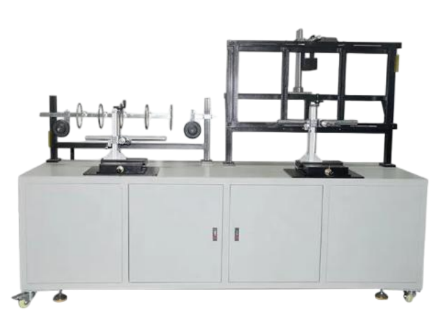
SL-7606 Wire & Cable Resistance to Fire Mechanical Shock Tester is a professional fire resistance testing apparatus designed to verify circuit integrity of cables subjected to fire alone or fire with mechanical shock, in accordance with BS 6387 and IEC 60331 standards.

Application

This test apparatus is used for testing cables required to maintain circuit integrity when subjected to fire alone or fire with shock. The test condition is based upon a flame with a controlled heat output corresponding to a temperature of at least 750°C, or fire with shock at a temperature of at least 830°C.

The wire and cable fire tester is used to test the fire resistance of cables for wiring or grid applications, burning in a flame of not less than 750°C and 950°C to verify the integrity of the cable to maintain the circuit.

Test Standards
  • BS 6387
  • IEC 60331 (customer requirement)
  • IEC 60331-11 & 12:2002
  • IEC 60331-21 ~ 23:1999
  • IEC 60331 Part 11 — Fire alone at a flame temperature of at least 750°C
  • IEC 60331 Part 21 — Cables of rated voltage up to and including 0.6/1 kV
  • IEC 60331 Part 12 — Fire with shock at a flame temperature of at least 830°C
  • IEC 60331 Part 31 — Fire with shock, cables of rated voltage up to and including 0.6/1 kV

Dimensions: 1750 mm (W) × 680 mm (D) × 1400 mm (H)  |  Weight: 160 kg

Equipment Composition
  • Resistance to fire alone
  • Resistance to fire with water
  • Resistance to fire with mechanical shock
BS 6387:2013 Test Devices
Water Spray Device — Protocol W (Resistance to Fire with Water)
Water spray device for BS 6387 Protocol W resistance to fire with water testing of cables
Water spray device for Protocol W — resistance to fire with water.
Mechanical Shock Device — Protocol Z (Resistance to Fire with Mechanical Shock)
Mechanical shock device for BS 6387 Protocol Z resistance to fire with mechanical shock testing of cables
Mechanical shock device for Protocol Z — resistance to fire with mechanical shock.
Machine Features
  1. The sample support device holds the sheath or protected end of the cable horizontally. One end is clamped by a fixed clamp to prevent movement, while the other end supports the sample. The middle of the cable is supported by two metal rings spaced 300 mm apart. The metal ring and other metal parts of the supporting device are well grounded. The inner diameter of the metal ring is approximately 150 mm, using a round bar with a diameter of 10 ± 2 mm.
  2. The ignition source is an American AGF propane ribbon burner with a nozzle length of 500 mm and a nominal nozzle width of 15 mm. The nozzle has three rows of staggered holes with a nominal diameter of 1.32 mm and a center distance of 3.2 mm. Small holes on each side of the nozzle serve as pilot holes to maintain flame combustion, with a dimensional tolerance of ±5%.
  3. An imported mass flow controller regulates the gas and air flow, with a reading accuracy of not less than 1.5%.
  4. An imported pressure reducing valve provides an outlet pressure of 0.1 MPa ± 3 Pa.
  5. An imported pressure gauge provides a 0–200 kPa pressure range.
  6. An imported Omega thermocouple with a diameter of 1.5 mm is used for burner temperature calibration.
  7. The burning test time can be set, with automatic gas cut-off.
  8. Standard test software displays burner calibration temperature, propane flow, and air flow.
  9. The test is applicable to cables with rated voltage of 0.6/1.0 kV and below.
  10. During the test, the current used for continuity inspection passes through all conductors of the cable. This current is provided by a three-phase star transformer with sufficient capacity to maintain the required test voltage when leakage current is allowed. At the other end of the sample, each conductor or each set of conductors is connected to a pointing device (LED indicator) to form a current through which data can be obtained in the computer software.
  11. The voltage setting can be entered via computer for automatic voltage setting, and can also be fine-tuned through panel buttons.
  12. The test circuit current protection adopts a fuse conforming to the D II type specified in GB 13539.5, with a standard 2A fuse that is easy to replace. Imported miniature circuit breakers protect each test circuit.
  13. The current and voltage data of the test cable are digitally displayed through the secondary instrument. The test current accuracy is 0.001 A, and the optimal test current is 0.25 A.
  14. Real-time measurement data of all currents and voltages are collected by computer to generate current and voltage curves, showing the current and voltage curves of each cable under fire conditions and determining fire resistance performance. Further analysis of the cable as a function of fire time can be made. Final data is stored in a computer database and a standard report is generated for easy access.
  15. Before the test, the flame temperature is calibrated using an imported armored thermocouple. The calibration temperature is collected by computer for at least 10 minutes, and the fire mode is selected in the computer. According to the fire supply mode, the computer performs steady-state sampling and difference calculation based on the collected temperature and provides a verification report. The report is saved and stored in the database to ensure the reliability and authority of the verification.
  16. During the test, both gas and auxiliary air are controlled by mass flow controllers and mixed through a venturi. The computer automatically controls the flow valve, and data is recorded in real time in the database. The computer automatically controls the gas and auxiliary air ratio to ensure full combustion, producing a stable flame and stabilizing the flame temperature.
  17. When the circuit is normally energized, each circuit uses an imported indicator light. When the line is incomplete under flame conditions, the corresponding circuit indicator is extinguished. The computer automatically determines the current state and controls the sound and light alarm.
Main Parameters
  1. Heat source: ribbon-type propane gas burner.
  2. Structured with 3 rows of cross holes; average front width of burner: 15 mm; hole diameter: 1.32 mm; distance between centers: 3.2 mm.
  3. A polished hole row in the pilot hole for flame preservation on both faces of the burner plate.
  4. Two thermocouples are horizontally installed, separated 45 mm left and right of the burner centerline, to check temperature.
  5. Mass flow controllers regulate gas and air flow, with accuracy not less than 1.5%.
  6. Software displays burner calibration temperature, propane and air flow rate, etc.
  7. Current is provided by a three-phase star transformer with sufficient capacity to maintain the required test voltage when circuit integrity cannot be maintained.
  8. Conductor connection indicator (LED indicator) to form a current.
  9. Voltage value is automatically set by software and adjusted by a panel controller.
  10. Digital display of current and voltage data, with current accuracy of 0.001 A.
  11. Current protection using a 2A fuse.
  12. Real-time measurement data of all currents and voltages are collected by computer, and current and voltage curves are generated.
  13. When circuit integrity cannot be maintained, the corresponding indicator lamp is extinguished, the computer automatically determines the state and records the time, and sends out a sound and light alarm.
Technical Specifications
Test station 1 station, one sample at a time
Test size Length > 1200 mm
Sample bracket Three bracket rings in the machine. During the test, the sample is placed on the bracket ring and fixed with two side fixtures. The inner diameter of the metal ring is approximately 150 mm.
Stainless steel test carrier, bearing 30 kg
Combustion gas Propane with purity of 98% (customer supplied)
Combustion supporting gas Compressed air (air pressure needs to reach more than 10 MPa)
Timer 0 to 99.99 s/m/h, arbitrary setting
Flame temperature 1000°C
Power supply AC380 (±10%) V / 50 Hz
Power 1 kW
Trolley size L450 × W910 × H540 mm
Sample bracket size L1200 × W430 × H700 mm
Control chamber size L1000 × W1000 × H1750 mm